Garrattfan's Modelrailroading Pages
AD60
2.1 Detailing the front unit
|
Instructions [133] to [170], page 16-18 of the instruction manual |
|
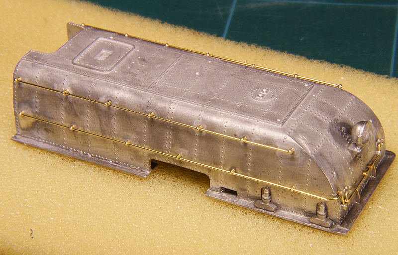
Once the the bulk of the front tank is done, work on the details can start. As the tank is made of white metal the entire construction is done with white metal solder (80C) with few exceptions. |
|
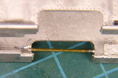 |
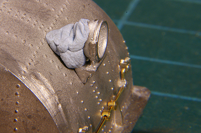
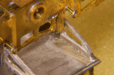
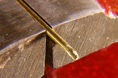
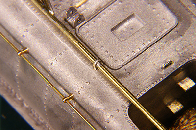
[133] tells you to drill out the two dimples in the inside of the cutaway. Have DJH ever given thought how to do that with two opposing holes. And how to put a piece of wire in them? I guess not. I carved a slot in the backside of the tank, left on the photo (the photo is shot from the inside of the tank) until I reached the dimple on the opposing (right) side. Then I had enough room to place my shortest drill and drill the hole on the opposite side. I inserted the brass wire and soldered the slot. |
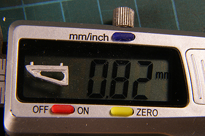
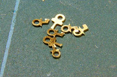
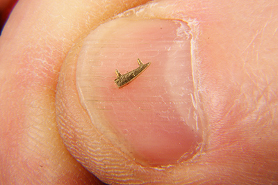
The front fillets are tiny. |
Very tiny indeed. |
[136] The front fillets are distinguished from the rear fillets by the fact that they have two spigots instead of one. Yet decusp them on all sides. Wear an apron, sit close to your desktop. If you drop it, chances are it will land safely on the table or in your apron. Avoid using pliers, they have a tendency to snap and launch these smallest of small parts at maximum velocity. You may have to spend the better part of an hour to retrieve it. |
|
 |
[136] If you drill the holes in the tank just undersize you can press fit the fillets. This makes soldering easier as they are already stuck into place.
|
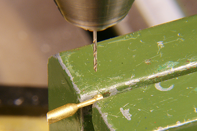 |
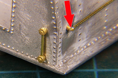
[137] Next job is attaching the junctions of the electrical conduits. Use a fresh sharp 0.5 mm drill. Drill carefully, checking again and again, no deeper than needed in the right-angled junctions.
|
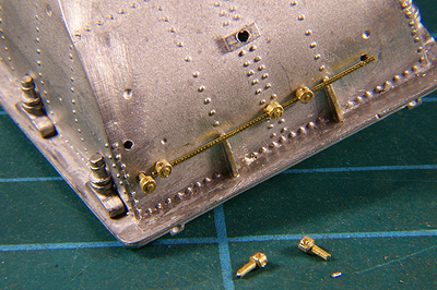 |
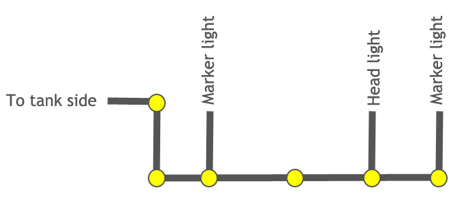
This the order of the junctions on the front of the tank and the consequent drilling scheme.
One piece of wire is fed through the five junctions. The wire is just long enough the fit between junction 1 and 5. The junctions are then soldered from the inside of the tank where possible. Some tweaking may be needed to prevent the fillets from interfering with the conduit. |
 |
|
 |
[138] Marker lights added. Again soldering takes place from the inside. The conduits are secured by placing a tiny scrap of 80C solder on a seam and then heat it. Use solder sparingly to keep the need for cleaning down. |
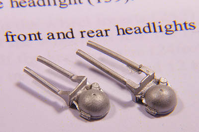 |
[139] Front and rear headlights are different.
|
 |
Soldering the headlight is not so easy as it seems, because the heat will do nasty things with your fingers. I used BluTack to keep the headlight in place. |
 |
Oh yes, before soldering I drilled the headlight with a 0.7 mm drill. I want to install an LED later. I also drilled a corresponding hole in the water tank behind the headlight to feed the wiring into the tank. |
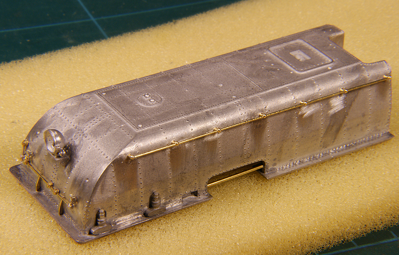
Next thing is to attach the handrails. I drilled the dimples of the knobs just a tiny bit smaller than the knobs (about 0.05mm) so I could press fit them in and solder them from the inside without letting them fall out again. Take care to drill perpendicular to the surface of the tank. Every knob needs a quick pass of a 1.0 mm drill to chamfer the openings on both sides but ever so lightly!! Finally pass a |
|
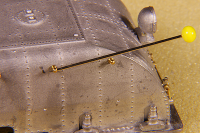 I used a pin to align the holes. |
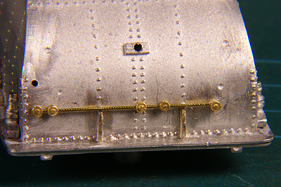
0.5 mm drill through the hole to clean it out, otherwise you may run into trouble while feeding the wire through it, the play in the holes can be tight. Position an end knob (front or back, whichever you prefer). Use a pin to align the hole in the direction of the handrail and solder it to the tank. Next slide the other six knobs on a straight piece of 0.45mm wire. Position all six knobs in their respective holes. Solder the other end knob to the tank from the inside if possible. Check if the handrails sits straight and both end knobs line up nicely. Then solder the other five knobs, checking again and again. Finally solder the one handrail knob were the wire runs through to fix the wire permanently. Cut off any excess wire and carefully file it flat at the end knobs.
|
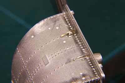
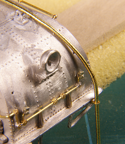
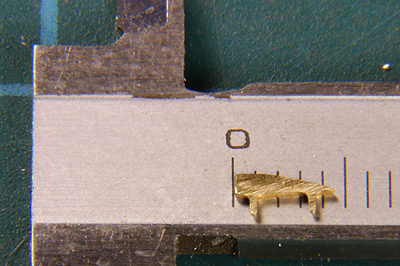
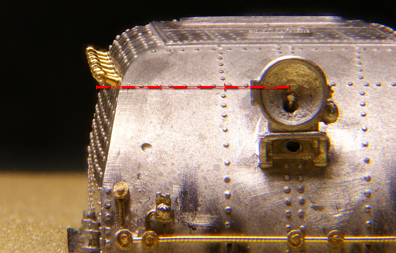
Take a peek along the knobs to see if they align correctly. "Good enough" was my verdict with the naked eye. On the photo they show not to align completely, especially the first two knobs. But remember, this is under extreme magnification. In reality the differences are minute, you won't see it under normal viewing conditions. I have added a scale bar in the photo, indicating millimetres (15 in total). |
|
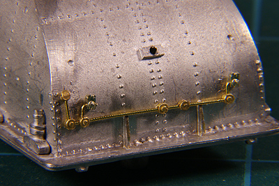
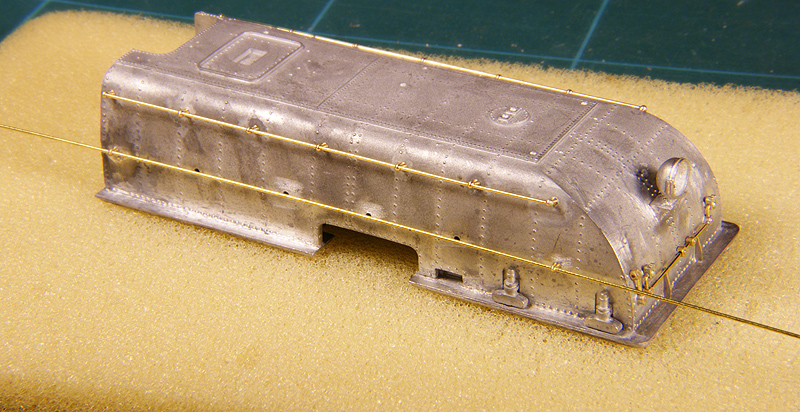
The conduit, often mistaken for a handrail, under construction. Do not forget that the conduit needs shorter knobs. Guess how I found out. |
|
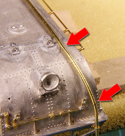
The conduit is bent around the corner and fed into the junction. It needs some careful bending. Take your time to do it right and, if need be, do it over. Keep the rear end of the wire long enough so if the front end goes wrong you can snip it off and continue trying to get the right bends without having to throw away the entire wire because it got too short. Only after the front bends are good enough fix it on one knob and cut the rear end. BUT cut it a little short so it fills about half the end knob at the rear. It will later have to take up a conduit from the rear. |
|
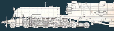
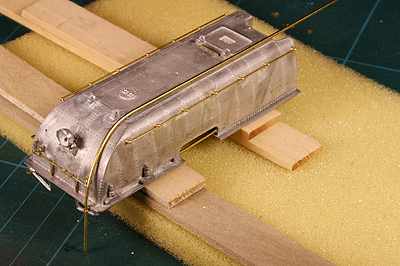
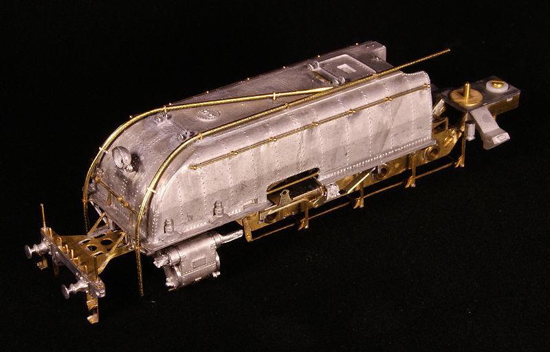
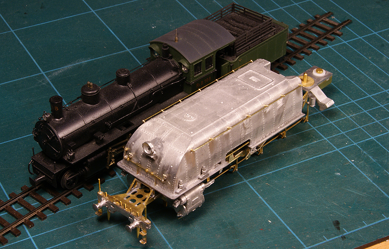
Just for the sake of comparison. Even only the front unit of an AD60 is as big as a G4/5 of the Rheatian Railway. |
|
 |
[154]-[164] The tank deck and fallplate are connected by a piece of 0.5mm wire. First fold the hinges and solder them with 180C |
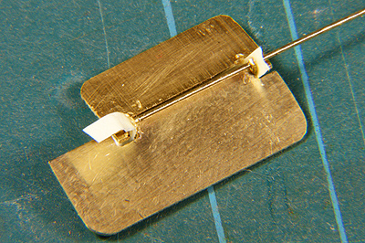 |
Take two pieces of paper, punch a tiny hole with a pin and grease them. Feed the wire through with the greasy paper between the hinges. Clean the outer end that passed though the paper from any grease. It is essentially the same technique as soldering the valve gear of a steam locomotives, like I elaborated during the NGG16 project |
 |
Solder them on the outside with just a quick pass of the iron (otherwise the paper will burn and loose it protective effect) and snip off excess wire. |
 |
To ensure a better grip first tin the backside of the deckplate with 140C solder ... |
 |
... and then solder it into place (80C). The manual suggests glueing. It is just whatever you prefer. |
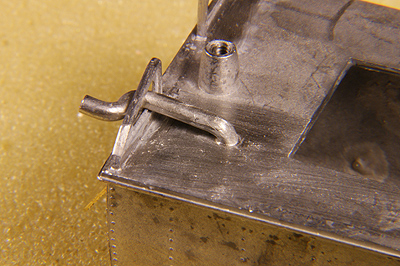
[162] At this stage the DJH manual leaves you head scratching again. "Fix in place the elbow (148), and junctions (153x2), joining these with 0.4mm wire as shown."
After giving it a long thought I concluded that [162], though in one semantic sentence, actually consists of two separate instructions that have nothing to do with each other whatsoever. Then I also realised that [162] must be combined with adding at least one of the four support plates mentioned in [170], as the elbow really does interfere with it. Actually the elbow has a special notch to position it nicely.
So please read: [162a] Fix in place one support plate (156) as per instruction [170]. Fix in place the elbow (148).
|
|
 |
[162b] The rear of the tank also has some conduits and junctions. I overlooked that fact and had to shorten the already mounted wire in the rear knob on the side of the tank. So I took it out again snipped off just a few tenths of a mm and replaced it. If you realise this in advance you could keep the wire a tiny bit shorter, saves you all the trouble |
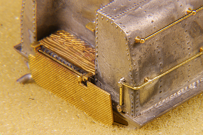 |
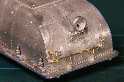
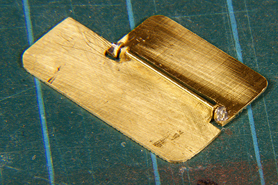
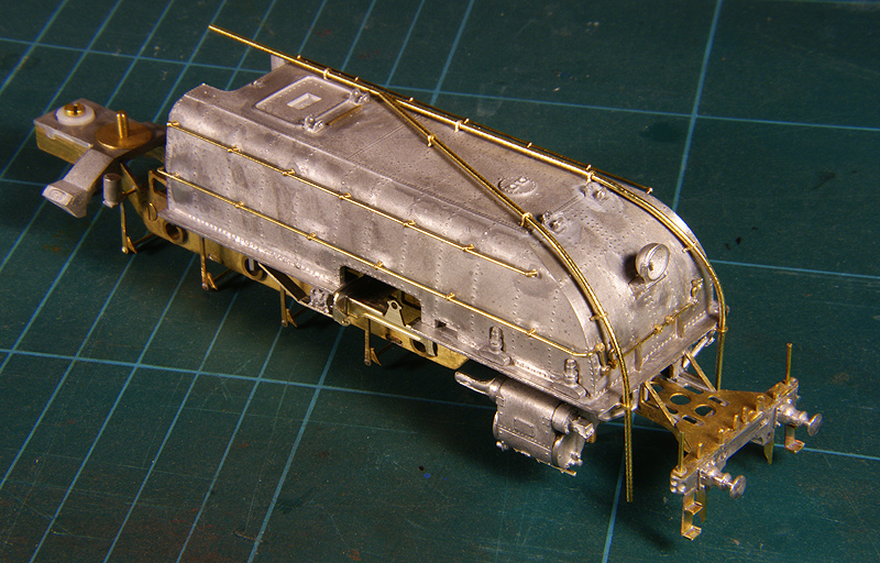
Well, it looks like this after I corrected things. Not too bad, eh? |
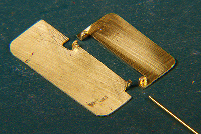
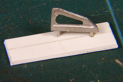
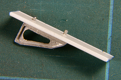
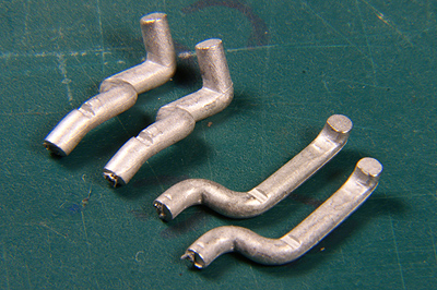
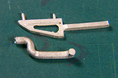
Two types of elbow |
The correct elbow and support plate corresponding with [162] |
 |
[170] The manual tells you to shorten the lugs to 0.8mm. As tolerances are tight, and eight lugs need to be cut to size I figured out a small helper of 0.8mm styrene with two holes in it. In hindsight I could even have kept it simpler. A square piece with just one hole would have done the job. That's for you to try. |
 |
It was now simply a matter of inserting the support plate and snipping the lugs off |
 |
Well? Good enough, I'd say |
 |
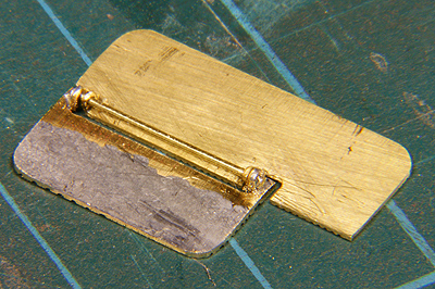
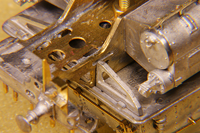
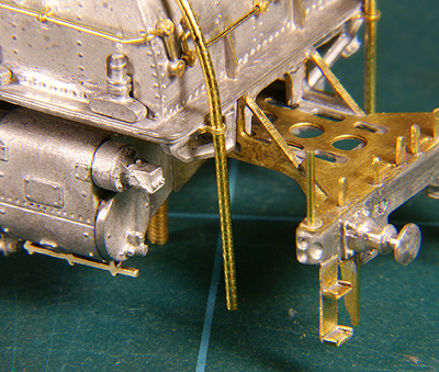
First the support plate was spot soldered in place, then the elbow was offered up and once I was happy with it I soldered everything solid. While being at it anyway I also added the other support plates, one of them just visible at the top of the photo |
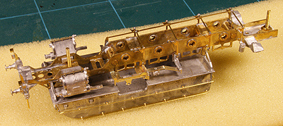 |
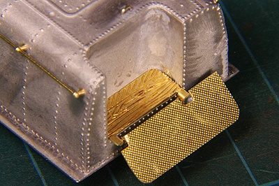
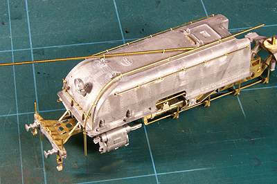
Next thing is to try and fit the frame to the superstructure. |
 |
At the front I had a nice and clean fit. |
 |
But the rear gave some trouble. Now is the time to correct that. It needed some twitching and scraping. Nothing much really, but do not force anything as the support plates are made of white metal and buckle or tear all too easily. |
 |
Once that was done I turned to completing the detailing of the superstructure.
[164] The sound pipe holders meant again a nice filing and cleaning job, making your fingers ache after completion. |
 |
Bending the sound pipe from 1.0 mm brass wire is by no means an easy job. First the brass is relatively hard. Second it needed to be bent in a double curve while following the shape of the front tank with a widening distance but within a few tenths of a millimetre! Simply take your time and use your eyes and judgement well. |
 |
The sound pipe should slide in the holder without any kind of strain. |
 |
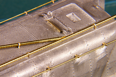
The locations where the sound pipe is double-curved. The upper bend to the left and down. The lower bend to the right and down. Work your way carefully through the material, avoiding sharp bends. Try and fit, again and again. Once satisfied I soldered the holders in place, when possible from the inside of the tank. |
 |
To fit the other sound pipe and to make a clean joint first two holders are temporarily soldered in place. These two position the sound pipe under the right angle. |
 |
Making this angle may take more than one attempt, but the more exact you work the better the result is. |
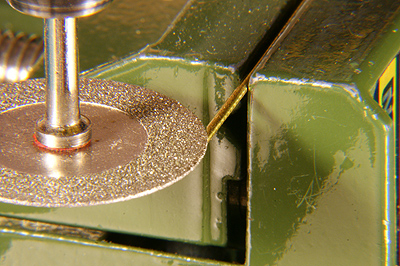 |
To make the seam as small as possible I used a disk to make a hollow in the wire. |
 |
Like this. Some filing finished the job |
 This sound pipe also features the double-curving. |
|
 |
The ends are left too long now. Later, when the loco is on its wheels, it will be cut to length. |
 |
Just beautiful |
 |
One small solder spot is enough to secure both sound pipes. |
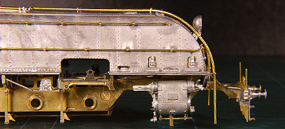
 The end result |
|

Sign my
GuestBook